Ultima Single Fire Ignition Wiring Diagram – Let’s begin by looking at different types terminals found on an ignition switch. These terminals comprise the Ignition switch and Coil and the Accessory. Once we know the purpose of each kind of terminal, it is possible to determine the components of the ignition wiring. In addition, we will discuss the functions of the Ignition switch and Coil. We will then focus on the accessory terminals.
Terminals for the ignition switch

An ignition switch has three separate switches that feed the battery’s current to various destinations. The first is used to turn on the choke through pushing it, while another switch controls the ON/OFF position. Different manufacturers have different colour-coding systems that correspond to the conductors. OMC utilizes this method. Connectors can be attached to the ignition switch in order to add an electronic Tachometer.
Even though some of the ignition switch terminals might not be original, the numbers of each one might not be in line with the diagram. Examine the integrity of the wires first to ensure they’re connected correctly to the ignition switch. This can be accomplished using a cheap multimeter. After you’re satisfied with the continuity, you can place the new connector. The wiring loom for an ignition switch that is supplied by the factory will be different from the one in your car.
In order to connect the ACC outputs to the auxiliary outputs on your car, you need to first understand how these two connections work. The ACC and IGN connectors are the default connections of the ignition switch. While the START, IGN, and ACC terminals are the primary connections to the radio or stereo, the START/IGN terminals are the primary ones. The ignition switch is responsible for turning the engine of your car on and off. On older cars, the ignition switch terminals are identified with the alphabets “ACC” as well as “ST” (for distinct magnet wires).
Terminals for coil
The terminology used to determine the model and type of the ignition coil is the first thing. A basic ignition wiring diagram will show a variety of terminals and connections, which include two primary terminals and two secondaries. Each coil is equipped with a distinct operating voltage. To determine which type of coil you have the first step is to test the voltage at the S1 primary terminal. S1 should be tested for resistance in order to identify if the coil is type A, B and/or C.
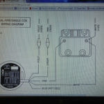
The chassis’ negative must be connected to the side of low-tension. This is exactly what you can see on the diagram of wiring. The high-tension supply provides positively directly to spark plugs. It is required for the purpose of suppression that the metallic body of the coil is connected to its chassis, however, it is not necessary. You will also see the connections between the positive and the negative coil terminals on the ignition wiring diagram. Sometimes, a defective ignition coil can be identified by a scan done in an auto parts shop.
The black-and-white-striped wire from the harness goes to the negative terminal. The positive terminal receives the other white wire, which has a trace of black. The black wire is connected to the contact breaker. You can check the connections with a paperclip to take the wires out from the housing. It’s also essential to make sure the terminals do not bend.
Accessory terminals

The ignition wiring diagrams show the various wires that are used to power the various components. Each part has four distinct colored connections. For accessories, red is for starter solenoid, yellow is for battery and blue for accessory. The “IGN” terminal is used to turn on the car, turn on the wipers, as well as other features. The diagram shows how to connect the ACC and ST terminals to the rest of the components.
The terminal BAT connects the battery to the charger. The electrical system cannot begin without the battery. A dead battery can cause the switch to not turn on. A wiring diagram can show you the location of the battery of your car. The accessory terminals of your car are connected with the battery as well as the ignition button. The BAT terminal is connected to the battery.
Some ignition switches come with an additional position. It allows users to connect their outputs to a different place without having to turn on the ignition. Sometimes, customers want to utilize an auxiliary output that is separate from the ignition. For the auxiliary output to be used, wire the connector in the same color as the ignition. Connect it to the ACC end of the switch. Although this is a great option, there’s a thing you should know. Most ignition switches are configured to show an ACC status when the vehicle is at either the ACC or START position.
Gallery of Ultima Single Fire Ignition Wiring Diagram

Gallery of Ultima Single Fire Ignition Wiring Diagram


