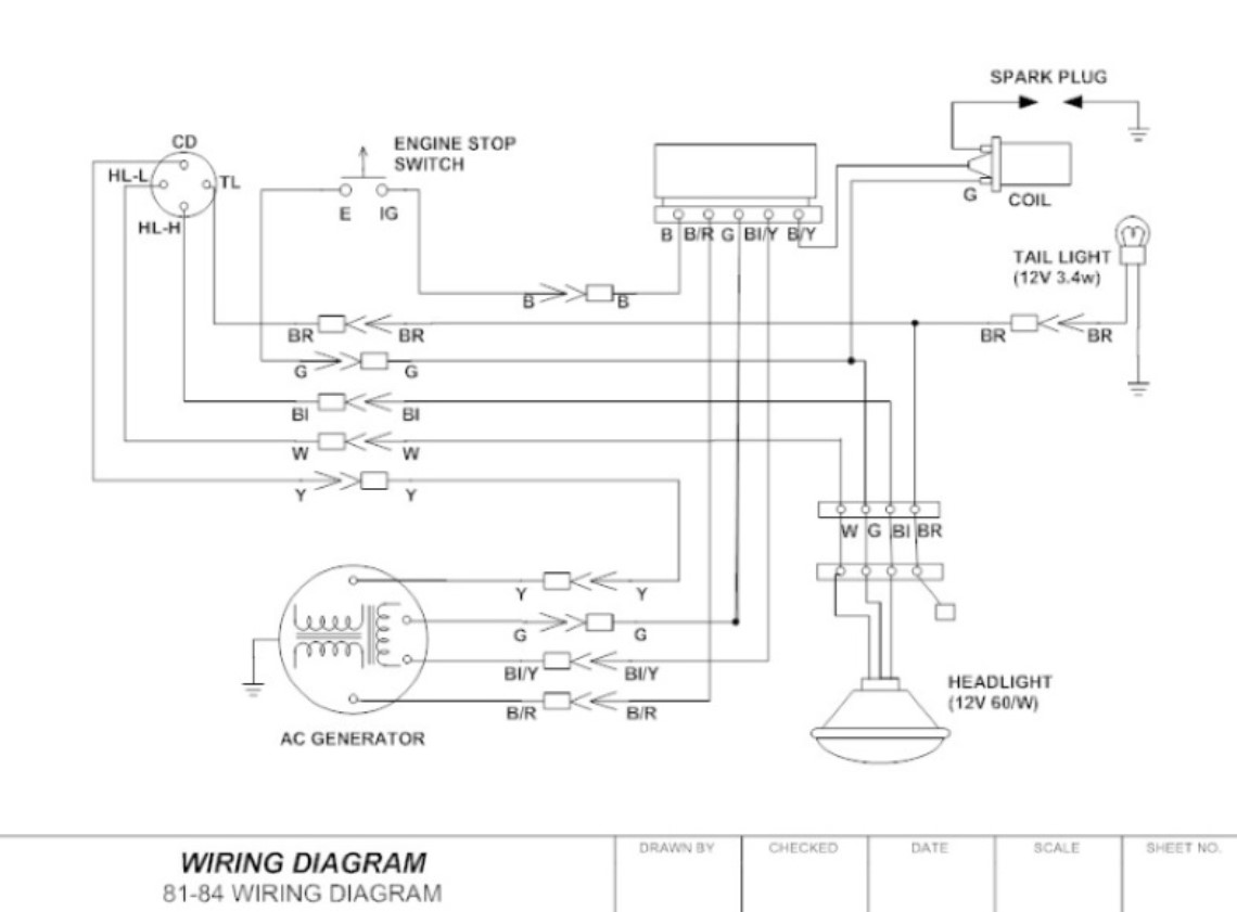
A wiring diagram is an understandable, traditional pictorial representation of an electrical circuit. It depicts the electrical components of the circuit in simplified representations, usually in a grid format, and the common power and ground connections among the different devices represented graphically. The simplified diagrams allow you to see the circuits’ inner workings, such as how circuits are interconnected to each other and how they affect the larger circuit. The wiring diagrams also show the potential energy sources for generating electric current. This article discusses the three types of wiring diagrams, and how they are used in today’s power systems.
3 Types of Wiring Diagram
Direct
A direct wiring diagram, sometimes called an electric circuit drawing, or DC diagrams, is a visual representation of electrical connection through the component’s terminals. There are usually three to four types of terminals: earth, power, and neutral. There may be two kinds of connections: direct and alternating current. With this type of wiring diagram, the component’s earth wire is in contact with the power source; the other two wires carry power from the source to the part to be connected, and the neutral wire connects the part to the earth. This visual representation makes it easier to connect the parts.
Intermediate
An intermediate wiring diagram, sometimes called an NCWK, is like a simplified CDWK. This type of visual representation provides more information than a direct Wiring diagram, such as power points and ground loops, making it useful in determining physical locations. A home builder can use the physical location data to help with location optimization when designing the house.
Complex
These are complex wiring diagrams that more than usually include all the necessary connections. The best diagrams for large-scale projects must be drawn on a scale model of the entire construction project. The interconnecting components of a complex system are represented by individual wires that run between each component. These can also include several types of connections, such as thermal expansion valves, refrigeration lines and fans. When designing a new home or remodeling an old home, you must take into account the connections involved.
The final kind of Wiring Diagram is the universal design Wiring diagram. This is designed to allow the electrical connection among any number of components. For instance, it could include the components of a thermostat, wall mounted lights and windows, ceiling fan and air conditioning unit. The advantage of using this type of Wiring Diagram is that it allows easy construction.
Benefits of Wiring Diagram
Wiring Diagrams can have several uses. It helps avoid costly mistakes. For instance, it avoids costly mistakes during installation. You can trace an electrical circuit using a wiring diagram and easily find the appropriate connections without having to read through your blueprint. This will save you both time and money.
Wiring Diagrams are often found in electrical engineering textbooks. You should refer to these books for the correct diagrams. If you want to create a Wiring Diagram on your own, you must follow certain rules. Refer to the following 3-phase power Wiring diagram, which relates to the AC, DIN and grounded conductor connections:
Wiring Diagrams are very important to your home. Therefore, it is advisable to create a Wiring diagram design based on the layout of your house. The Wiring diagram representation will show you all the components you will need in the process of wiring your electrical devices. The Wiring Diagram representation will help you easily identify the components.
There are many reasons to use wiring diagrams. When you are about to make repairs or modifications to the electrical system in your house, you must refer to a wiring diagram to ensure that all the connections are well-placed. It will save you the time and effort in the long run. Before you start working, you don’t have to worry if the Wiring diagram you are using is in-dated. You can still use these older Wiring diagrams as long as they are valid according to the current rules of the state.
Wiring Diagram Symbols
Wiring Diagrams are usually produced by Wiring diagrams are found in different symbols that allow you to understand them easily. For example, Wiring diagram from electrical engineering uses different symbols compared to other diagrams. They are produced in black and white colors so that they are easier to be read. To make Wiring Diagram more understandable, it is advisable to place the different symbols on the diagrams.
The main reason for using Wiring diagram symbols is to help you identify a certain wire. The different symbols used in Wiring diagram help you know the purpose of a wire, such as short, long, medium and neutral. In case of a Wiring switch, you will notice that the wire that comes into contact with a certain wire has a different color than the rest of the wires. This way, you will know that the wire that needs to be controlled is identified with a symbol. Sometimes, when you are using a Wiring diagram, you need to switch between several symbols. It is important that you keep switching between the symbols to identify the wire that is being controlled.

