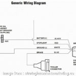
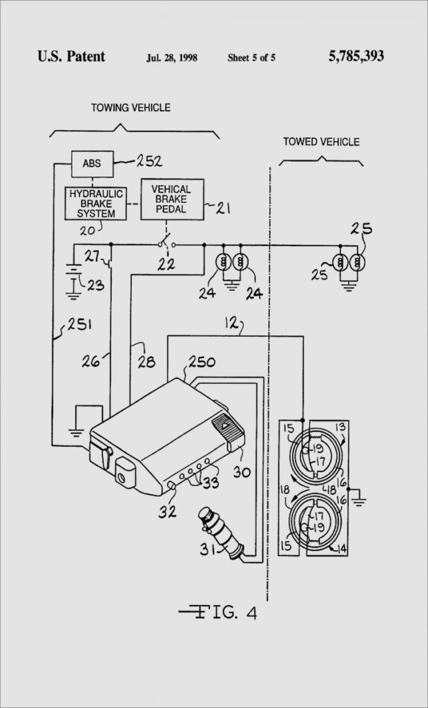
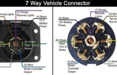
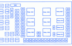
Agility Trailer Brake Controller Wiring Diagram – A wiring diagram can be a basic conventional pictorial depiction of any electric powered circuit, with its cables and connections represented as dots. It represents the power circuits components as simple shapes, with all the real power and terrain relationships between them as shaded sectors. In electric powered technology, a Agility Trailer Brake Controller Wiring Diagram is frequently utilized as an analogy to clarify the electric powered circuits to individuals unfamiliar with power design.
Agility Trailer Brake Controller Wiring Diagram makes use of internet wiring to symbolize actual physical relationships within a program. Digital Wiring Diagrams (VWD) is a type of pictorial display that enables folks to generate a wiring diagram of their process without having to produce actual models or drawings. This makes it easier to picture the wiring diagrams on paper or another surface as there are no actual contacts between the factors of a VWD. Because of this, diagrams made making use of VWD are usually simpler and easier to learn than their true-lifestyle equivalents.
How to Use Agility Trailer Brake Controller Wiring Diagram
There are numerous approaches to bring Wiring Diagrams. To begin with, the standard design applied can be a box. Two boxes can be utilized since the method, when a few boxes can represent each of the wire connections. Every couple of cases has distinct icons symbolizing the various electric powered links in between each set of cords.
The next thing to get Agility Trailer Brake Controller Wiring Diagram is to create a virtual version of the power icons coming from a reserve or any other image document. After that, these emblems are connected to a Wiring Diagram Author program to convert them to an actual reflection. When this is accomplished, you can easily notice that the Wiring Diagram is simply a collection attracting with electric symbols located across the pipeline. If needed, one could even affect the color of every wire, though most collections will remain the same.
It is easy to make maintenance at home constructing when a circuit is tripped, but mending an electric issue may be complicated. Most residence developing codes do not let much room for producing repairs except when the problem is very exclusive. Rather, it is best to contact an authorized electrician in the future and be sure the issue is fixed. Usually, it could be discovered without difficulty by phoning close to for the various businesses that provide Wiring Diagrams. Since the costs to get a wiring diagram are pretty low-cost, it is advisable to work with wiring diagrams when creating improvements.
Using a Agility Trailer Brake Controller Wiring Diagram provides for simple and easy swift recognition of electric elements. As a result restoring components much simpler, particularly if several parts should be replaced concurrently. When generating maintenance, it is very important understand that any modifications to components like terminals needs to be appropriately branded that it is crystal clear who produced what modify. Because so many elements make connections through a couple of cable, also, it is important to know which elements share relationships. Following a wiring diagram, it is very an easy task to establish and fix any electric component.
